






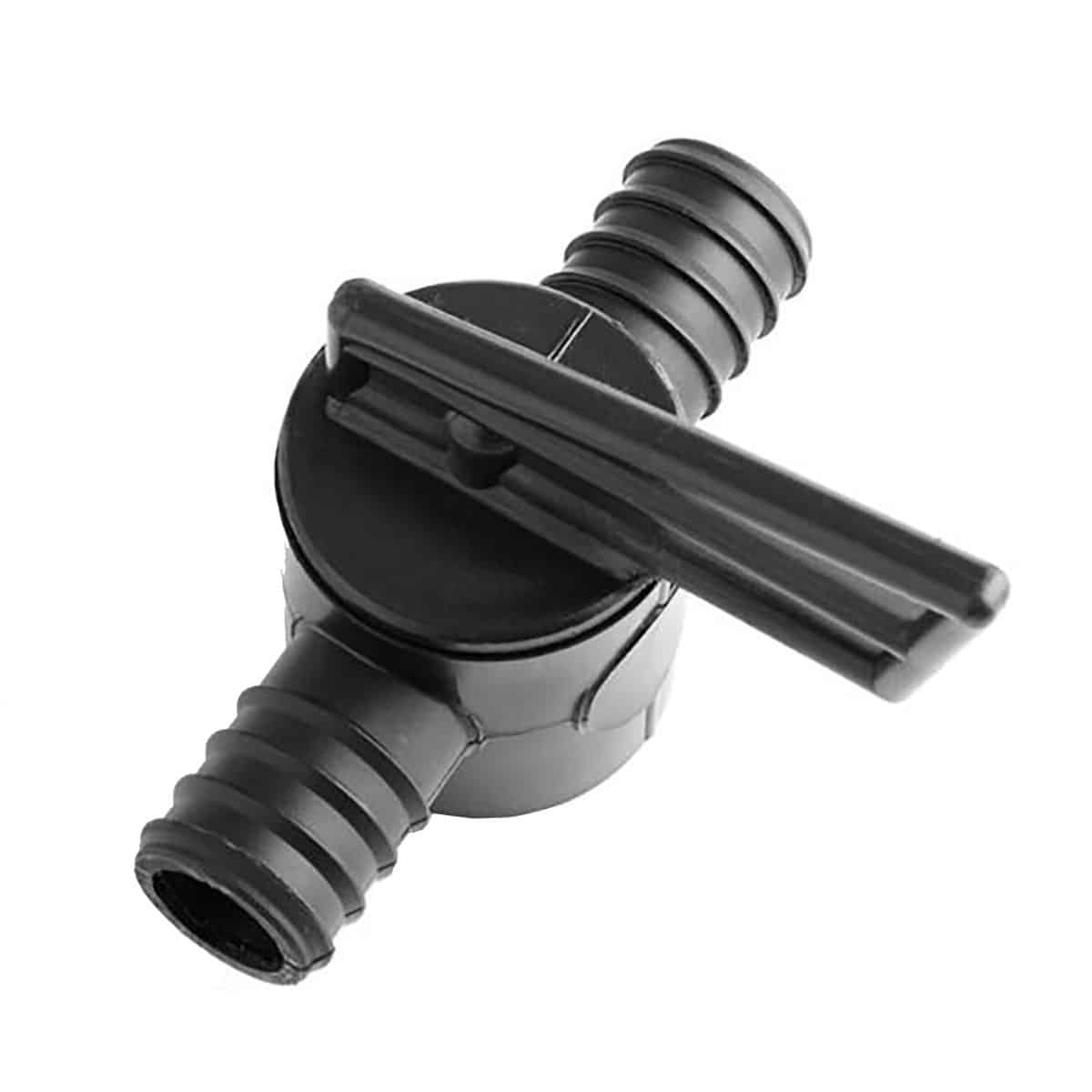
Inline Pond Hose Valves – Flow Control Hose Connectors
| Connection type | Hose to hose |
|---|---|
| Fitting type | Inline control valve |
| Quantity | One valve |
| Hose internal diameter | 1/2 inch (approximately 13 mm), 3/4 inch (approximately 19 mm), 1 inch (approximately 25 mm), 1.25 inch (approximately 32 mm) |
Inline valves with a hose connection at both ends. Choose ½, ¾, 1 or 1¼ inch to match the hose internal diameter. One valve supplied; hose and clips are separate. Check the operating requirements of your pump and connected equipment before restricting flow.
Price range: £7.95 through £14.95 (inc VAT)
Inline hose valves for a more manageable pond hose connection
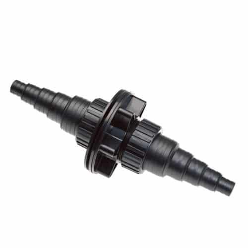
These inline hose valves join two lengths of compatible flexible hose and give you a local point at which to adjust the water flow. A valve can be useful on a small feature branch, where the amount of water needed by an ornament differs from the flow needed elsewhere in the system. The hose connection is at each end of the fitting, so you do not need to add separate threaded hosetails simply to connect a matching hose bore.
Choose the valve by the hose’s internal diameter. The four options in this range are ½ inch, ¾ inch, 1 inch and 1¼ inch. Each option supplies one valve. Hose, clips, additional branches and pumps are separate items. The size refers to the hose connection: it is not a promised flow rate, a pressure rating or the outside diameter of the hose.
Available hose sizes
| Hose internal diameter | Oasis reference | Connection arrangement |
|---|---|---|
| ½ inch, approximately 13 mm | PN044B | Hose connection at both ends |
| ¾ inch, approximately 19 mm | PN044C | Hose connection at both ends |
| 1 inch, approximately 25 mm | PN044D | Hose connection at both ends |
| 1¼ inch, approximately 32 mm | PN044DD | Hose connection at both ends |
Where an inline valve can help
A flexible hose layout often needs a little more control than a simple connection from pump to outlet. A decorative feature may need a gentler flow, or a branch may need adjustment after the hose route changes. An accessible valve lets you make that adjustment close to the relevant hose run. It also makes the direction of adjustment easier to identify when several pipes and fittings are grouped behind a filter.
Plan the valve position with the whole system in mind. Restricting one branch can change the flow in another, and reducing flow through a filter or ultraviolet clarifier can affect the way that equipment operates. Check the permitted flow range and installation instructions for every connected component. Do not use a valve to conceal an undersized hose, blocked strainer or poorly matched pump.
Selecting the correct bore
Read the size printed on the hose or measure a clean, undamaged end. A measurement across the outside includes the wall thickness and can lead to the wrong choice. Ribbed hose and reinforced hose can have quite different outside diameters despite sharing the same nominal bore. If the existing hose has stretched around an old fitting, check an unstretched section before ordering.
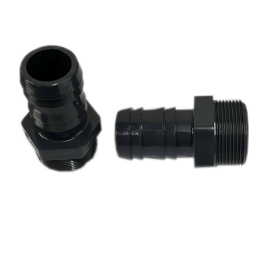
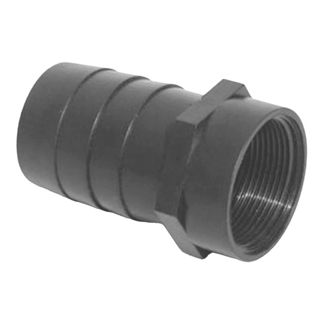
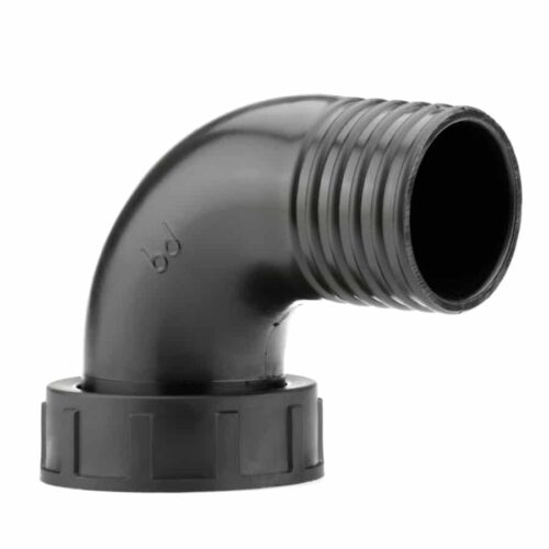
Use the corresponding size at both ends of the valve. Forcing a smaller hose over a larger connection risks damage, while tightening a clip around a loose fit is not a substitute for the correct fitting. If your installation also needs a threaded connection, compare our 1½ inch male threaded hosetail and female threaded hose adaptor. These are different connections and must be selected separately to suit the equipment outlet.
Positioning and fitting the valve
Switch off and isolate the pump before opening a hose run. Consider the water level on both sides and drain or otherwise safely isolate the affected section before disconnecting anything. Water can continue to move under gravity even after a pump stops, particularly where the hose is below pond level. Protect electrical equipment from any water released while working.
Choose a position where the control remains accessible and where the hose can approach each end without a sharp bend. Support the hose independently so its weight is not hanging from the valve. Leave enough room to inspect both joints, operate the control and remove the valve later. A fitting buried in a cramped corner may be easy to install but unnecessarily difficult to maintain.
Use a suitable hose clip where required by the hose and fitting instructions. Check that its adjustment range matches the assembled hose outside diameter. Tighten it sufficiently to secure the joint without damaging the hose or distorting the fitting. Do not apply solvent-weld cement to a barbed hose connection, and do not assume an adhesive intended for rigid pipe is suitable for your hose.
Restarting and checking the flow
Restore the system with the valve in the required open position, then make small adjustments while observing the actual outlet flow. Check both hose joints for drips and check again after the hose has settled. Make sure any connected filter remains supplied at its required rate. Never run a pump against a closed outlet unless its manufacturer expressly permits that operating condition.
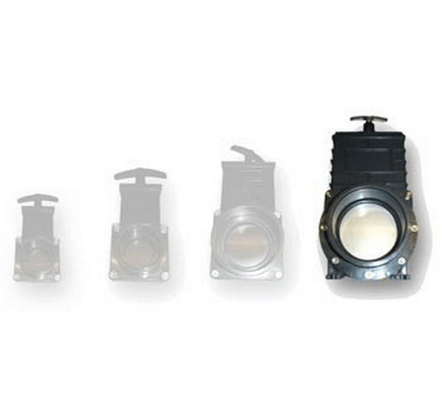
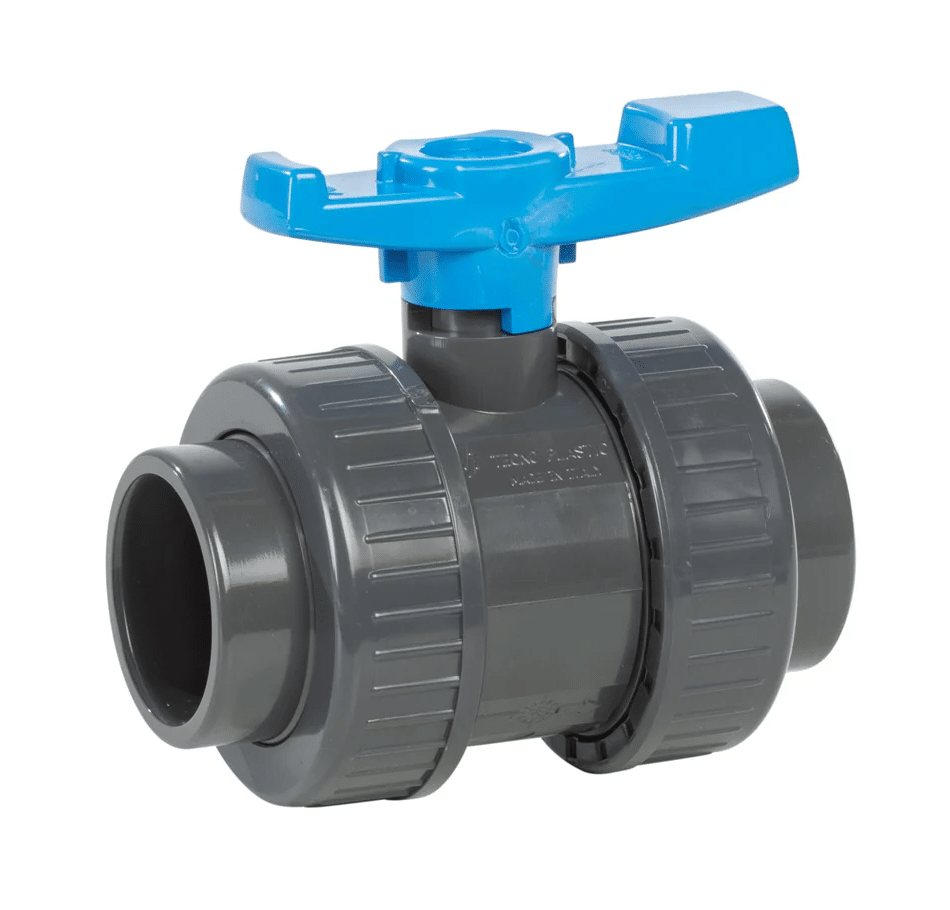
This fitting has no pressure or temperature rating stated in the supplied catalogue information. Do not treat it as a rated mains-water isolation valve, a hot-water fitting or a guaranteed emergency shut-off. Where a rigid pond pipe installation needs a different valve arrangement, our double-union pressure ball valves and Valterra slide valves provide other options to assess against that installation’s requirements.
Maintenance and practical checks
Inspect the valve when you check the rest of the hose run. Look for split hose ends, loose clips, leaks, stiff operation and anything pressing against the control. If operation becomes difficult, isolate and examine the fitting rather than forcing it with tools. Clean or replace worn parts as appropriate, and follow the connected equipment’s winter shutdown instructions where the system will be drained.




Reviews
There are no reviews yet.