






3/4 Inch Push-Fit Pond Fittings — Bends, Tee and Coupling
| Connection method | Push-fit |
|---|---|
| Nominal size | 3/4 inch |
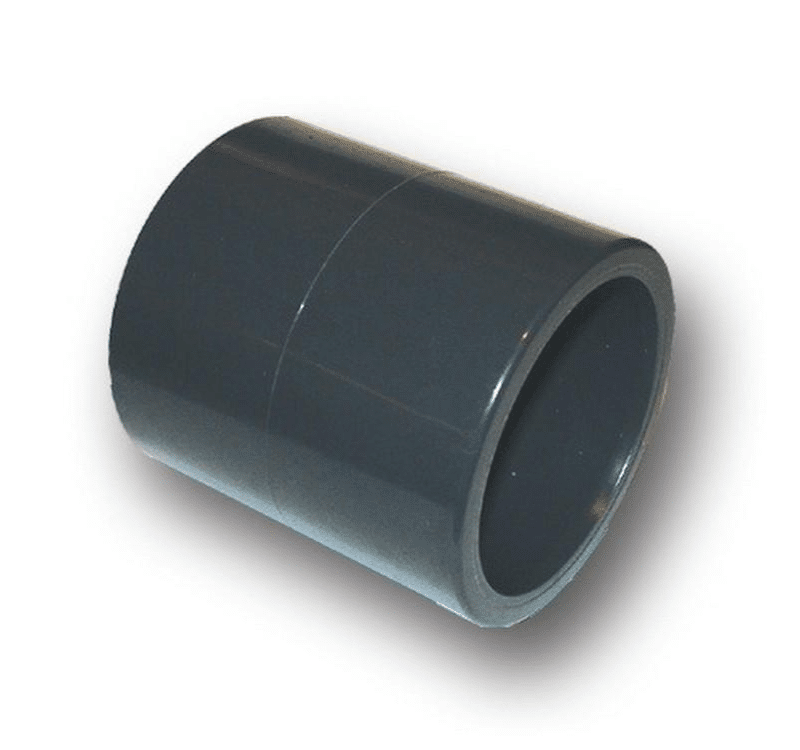
| Option | 3/4 inch nominal push-fit 90° knuckle bend, 3/4 inch nominal push-fit 45° obtuse bend, 3/4 inch nominal push-fit 90° swept tee, 3/4 inch nominal push-fit straight coupling |
Nominal 3/4 inch push-fit fittings: a 90° knuckle bend, 45° obtuse bend, 90° swept tee or straight coupling. One selected fitting; identify the matching pipe system before ordering.
Price range: £2.85 through £2.96 (inc VAT)
Three-Quarter-Inch Push-Fit Pond Fittings
These fittings provide the listed bend, tee and straight-coupling choices in the supplier’s three-quarter-inch nominal push-fit range. They are selected by their complete connection system and shape, so compare the existing pipe and joint arrangement before ordering a replacement.
Shapes and supplied quantity
| Selected shape | Quantity |
|---|---|
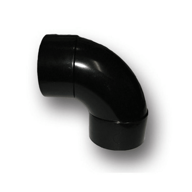
| 3/4 inch nominal push-fit 90° knuckle bend | One fitting |
| 3/4 inch nominal push-fit 45° obtuse bend | One fitting |
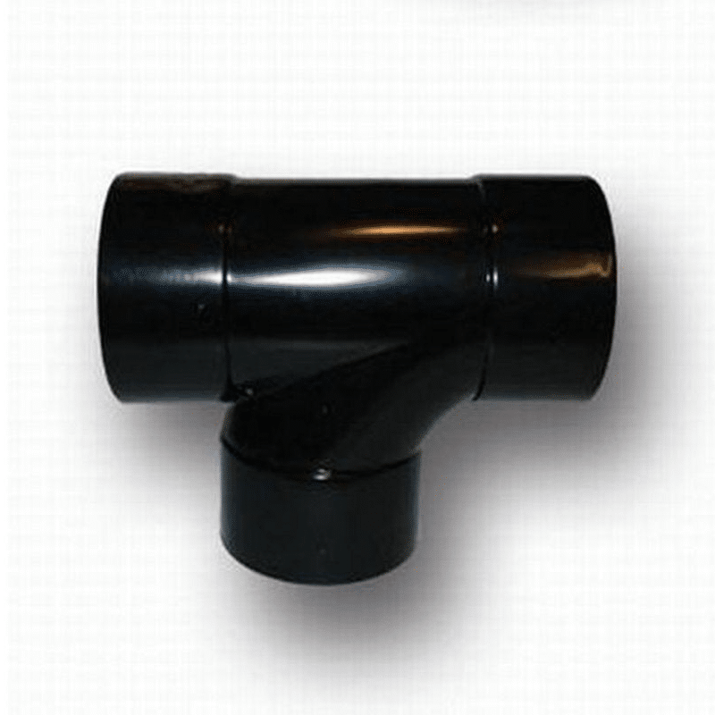
| 3/4 inch nominal push-fit 90° swept tee | One fitting |
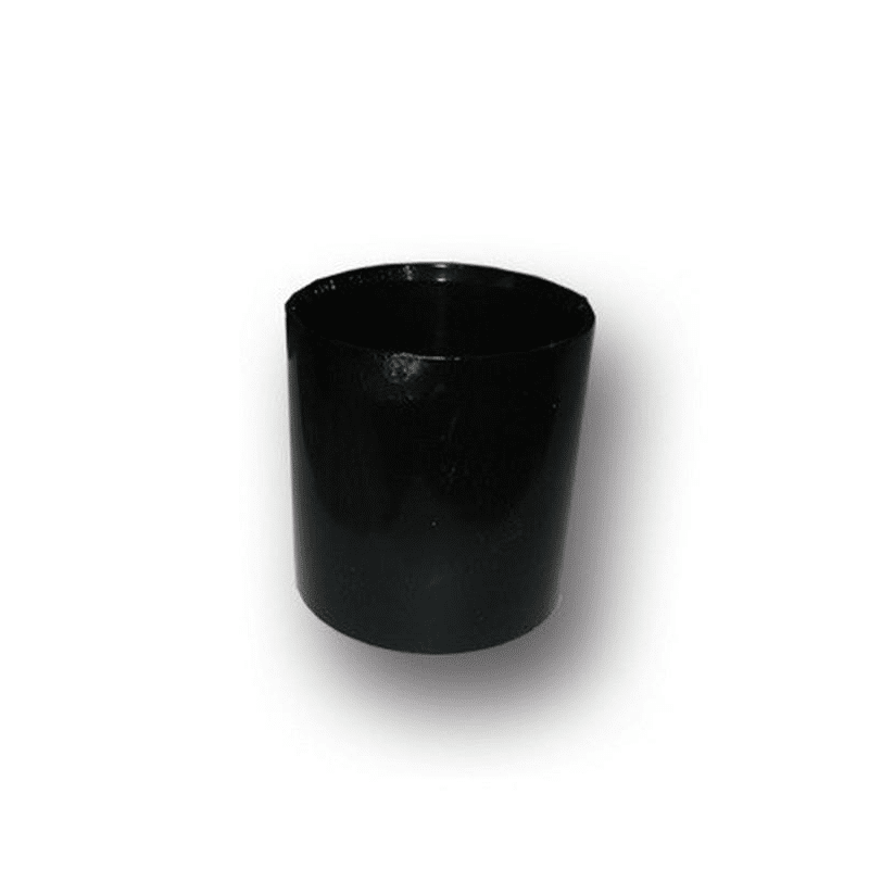
| 3/4 inch nominal push-fit straight coupling | One fitting |
Each option supplies one fitting, rather than a set of all four. Pipe, supports and other connecting parts are separate. The nominal inch designation does not identify a BSP screw thread, a hose bore or an automatically interchangeable 21.5mm solvent-weld component.
Choose the shape for the route
The 90° knuckle bend changes the direction of a compatible route through a right angle. The 45° obtuse bend makes a shallower turn. Choose the angle that suits the layout and access around the equipment, avoiding a series of unnecessary changes in direction.
The swept tee provides the listed 90° branch connection, while the straight coupling joins compatible sections along a straight route. Check the planned direction of water and the equipment’s installation guidance where a branch or discharge arrangement is involved.
Identify the existing connection standard
Inspect an undamaged existing fitting and the pipe it connects to. Confirm the actual system before replacing a component. Similar-looking parts may differ in socket dimensions and sealing arrangements, so an approximate measurement across an old joint is not enough to identify every push-fit system.
A push-fit connection should be assembled using the method intended for its pipe and socket. Do not convert the joint into a solvent-weld connection by adding glue, or force a threaded or barbed component into a socket that was not designed for it. Match the complete route rather than only the number in the product name.
Plan access before fitting
Measure the route, the available clearance and the position of the intended joint. Leave enough room to prepare the pipe end and seat it correctly. Consider how the assembly will be inspected, cleaned or removed during later maintenance.
Support longer sections of pipe independently so their weight does not rest on a small equipment port. Keep the route clear of sharp edges and moving equipment. A fitting that is aligned properly during assembly is easier to check than one held under continual strain by an unsupported pipe.
Work with the intended operating conditions
The nominal size and push-fit label do not establish a pressure or temperature rating for the complete installation. Use components documented for the service required by the pump, filter or other connected equipment. In particular, do not assume that a small waste or overflow fitting is interchangeable with a pressure-rated delivery fitting.
If you are changing an existing layout, record the original pipe size and connections before dismantling it. That makes it easier to compare the replacement and preserve access to a drain, valve or inspection point that the system needs to remain serviceable.
When replacing several fittings, label the removed parts by their position so that the route can be rebuilt accurately and the required angles remain clear.
Prepare the joint
Safely isolate the relevant equipment and drain the affected route before opening it. Inspect the receiving socket and pipe for damage. Make a clean cut where a new pipe end is needed, remove loose debris and follow the pipe system’s instructions for preparing the end.
Assemble the joint using the specified insertion and sealing method. Do not force a damaged or mismatched pipe into position. Check that any seal required by the actual socket arrangement is correctly seated and that the route is supported without pulling the joint out of alignment.
Check after restoring the water route
Restart the installation as the equipment instructions describe. Inspect every affected joint for leaks, confirm that the route remains correctly seated and watch the intended water flow. Keep the joint accessible while it is being checked rather than concealing it immediately after assembly.
Include the fitting in routine maintenance and recheck it after the equipment is moved. A repeatedly disturbed joint may need its components inspected or replaced; extra force is not a reliable repair for a damaged seal or an incompatible pipe end.
Compare other connection families
Our black waste 90° bends, black waste tees and black waste straight connectors belong to separately described ranges. For pressure pipework, compare imperial pressure pipe straight joiners. Select their actual standard and dimensions for the installation rather than treating all nominally similar fittings as the same product.




Reviews
There are no reviews yet.